Welcome to part four of the iRotary trilogy! This is the part where we complete the project, along with the OFFICIAL TRAILER at the very end (spoiler alert!).
The original goal of this post was to complete the project, but I have delayed writing it for so long, that I think it would be better if I just started from the beginning, and produced one, cohesive narrative.
As you may remember from part one, I am a very angry person. Especially when talking on the phone, I get easily pissed off, and nowadays there’s no good way to express my frustration. I miss the olden days, where you had a nice physical handset you could slam into the phone to relieve your tension, but mobile phones just don’t provide the same pleasure. Undeterred, I set out to create a rotary phone that was also a mobile phone.
Thus, the iRotary was born.
Project iRotary
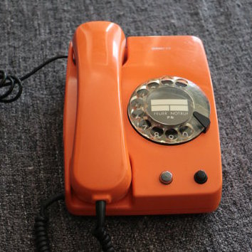 What a beauty.
I started by buying an old-school, legitimate rotary phone, which happened to be the same make and model as the one we were using when I was a kid. I got it in illustrious orange, because I wanted the iRotary to be as fabulous as it is ambitious.
That is the very phone in question, in the photo on the right, as it was on the first day I bought it, cables and all. That is also exactly as fantastic as it looks to this day, except today it has 50% fewer wires, which is presumably a good thing, as far as mobile phones go.
The entire build cost something like $150 in parts and $2000 in development time, as it took me about two full days to complete, spread out over a few months of doing something, waiting for parts, using them, waiting for more parts, etc. The first step, of course, was to take out everything unnecessary from the phone, and replace it with everything necessary.
Step 1: That’s Numberwang!
 Imagine taking this bad boy to the club!
The best candidate for connecting the phone to the GSM network and interfacing with the oldie components is, of course, an Arduino. The Arduino is ideal for reading the pulses of the rotary dial and converting them into an integer that I can then use to dial the phone number I select.
The communications part is easily handled by a GSM shield, which is a peripheral that connects to the Arduino (we call that a “shield”, on the streets). The shield is very easy to program, it comes with a library that provides most of the functions you need, such as reading SMS, making and receiving calls, sending DTMF, and much more!
The next step was to write some code to digitize the phone’s rotations into integers. The way a rotary phone’s dial works is this: After you rotate the dial, it starts rotating back, and that rotation pulses a switch, once for every number that passes by it. That means that, if you dial a three, the switch will pulse three times, as three numbers pass by it as the dial rotates back. To find which number the user dialed, simply detect how many times the switch opened and closed, and you have your number.
This was easily achieved with the following piece of code, which just adds a one to a variable every time the voltage from the switch changes from low to high:
void readPulses() {
    char pinPulse = digitalRead(PIN_PULSE);

    if (pinPulse == HIGH && edge == 0) {
        pulses++;
        edge = 1;
    } else if (pinPulse == LOW && edge == 1) {
        edge = 0;
    }
}
All that needs to happen after that is to aggregate the digits and make the phonecall when the number of digits is ten. That works because all numbers in Greece are ten digits long, except for phone sex lines, for which the code would be added later.
Appending digits to a string, one by one, is a fairly straightforward process, accomplished easily by the following code snippet:
void readDialing() {
    char digit;
    bool finalDigit = false;
    char pinDialing = digitalRead(PIN_DIALING);

    if (pinDialing == 1 && dialing == 0) {
        digit = getDigit();
        if (digit != -1) {
            number += (int)digit;
            showNumber(number);

            if (number.length() == NUMBER_LENGTH) {
                dialNumber(number);
            }
        }
    }
    dialing = pinDialing;
}
It didn’t actually place the phone call yet, as the shield wasn’t connected, but that was the next step. Here is the prototype in (preliminary) action:
It worked pretty well right off the bat, even with the old, dilapidated prototype phone I found. The rotary dial is surprisingly accurate, which it has to be, because otherwise you end up dialing the wrong number, with no idea that anything went wrong until a guy answers the phone when you’re calling your girlfriend, and you think she’s cheating on you and make a big fuss when in reality a switch just misfired. That is also why divorce rates fell sharply with the advent of touch-tone dialing. This also led to reduced violence against people whose phone number contained too many zeroes.
Step 2: No guts, no GSM
After successfully detecting numbers, the next step was to add the ability to make phone calls over the mobile network. I connected the shield to the Arduino and added the necessary code to allow it to place calls:
void dialNumber(String number) {
    call.Call(numArray);
}
Riveting.
Even though this step was pretty easy, it was exciting in that most of the functionality of a rotary mobile phone (rotary dialing and making phone calls) is already completed. Here it is in action:
This step posed a few challenges, though. The first was the matter of where in the phone the Arduino and shield combo can be physically placed, as there’s almost no space that isn’t used by one of the phone’s components. To solve this nigh insurmountable problem, I had to make a compromise: I removed the ringer bell, which I couldn’t power from a small battery anyway (it requires 50V), greatly reducing the phone’s authenticity. What was I going to do with a rotary phone that wouldn’t produce the distinctive “brrrrring” sound?
Then, inspiration struck! The solution was obvious: The phone would be in silent mode, out of politeness and consideration for all the people who might be annoyed by its incessant, but otherwise delightful, ringing.
Having solved two problems with one excuse, my excitement was beginning to soar. Another challenge that the project presented was that it needed a way to connect the shield’s audio input and output to the handset somehow. Excuses wouldn’t work here, as no self-respecting phone would also be deaf and mute for any reason, so I initially thought to buy a small speaker and microphone, and rejigger them in the headset. I was just about to order the pair, when a wild fancy took me: I would try the existing microphone and speaker first.
I quickly adjourned to my drawing board and sketched out a complicated schematic that consisted of a myriad of three cables and two connectors. Hastily connecting these together, I inserted the jacks into the shield’s input and output and placed a call.
- “Hello”, said my voice on the line. - “Hello!”, I excitedy replied. - “I can hear you!”, I told myself. - “So can I!”, boomed the reply.
The test was a rousing success. Not only were the existing components compatible with the shield, but they produced this amazing, authentic crackle and feedback, which I had completely forgotten about.
You see, the difference between a mobile phone and a rotary phone is that the former doesn’t play your voice back from the speaker. This makes you think that your voice is lower than it actually is (because you’re simultaneously plugging your ear with the handset), so you shout more, much like wearing headphones and listening to music while trying to talk to someone.
The rotary phone doesn’t do that, though. You can hear your voice in real time, as you speak (it’s called sidetone), which is very pleasant, and feels like you don’t need to shout for the other person to hear you. It’s a very nice effect that we don’t get nowadays.
Here’s the teaser for the final product:
The ringing sound is fake, but that’s Hollywood for you.
Step 3: 50% more steppy
Now that the audio, number detection and GSM were working, it was time to connect the rest of the controls, like the hook, button, and the weird LED-like thing that would show when the phone was booting.
A clean way to do this is with events. The Arduino doesn’t work that way, as you continuously have to ask “is this button pressed?” many thousand times a second, but one can rather easily fake an event-driven architecture on top of this with some code.
I wanted the lifting the handset from the hook to pick up the call if the phone was ringing, and to hang up a call in process if the handset was placed back on the hook. I also wanted any inputs to be ignored if the handset was on the hook.
Achieving this is easy with a state machine. That simply means that there’s one variable that always contains the current state of the phone, i.e. whether it’s idle, in a call, ringing, dialing, etc. Then, any events that pop up (such as “button pressed”) can just check what state the phone is in, and either perform the necessary action or do nothing.
Events
We can detect events the same way we’re detecting the dialed numbers, above. Namely, we’ll check whether the button’s input changes state (pressed or unpressed), and fire an event only when we detect the change (otherwise we’d be firing the event thousands of times, as it we kept asking “is it pressed?” and the Arduino kept replying “yes” thousands of times a second).
#define PIN_BUTTON_HALF 6

char buttonHalfEdge = 0;

void checkButtonHalfPressed() {
    if (digitalRead(PIN_BUTTON_HALF) == LOW) {
        if (buttonHalfEdge == 0) {
            buttonHalfPressed();
        }
        buttonHalfEdge = 1;
    } else {
        if (buttonHalfEdge == 1) {
            buttonHalfReleased();
        }
        buttonHalfEdge = 0;
    }
}
This particular button has two states, half-pressed and fully-pressed (or half-unpressed and fully-unpressed, as a pessimist might put it). The code above detects both, and the other events are handled in a similar fashion.
You can see what this looked like in the following video, where the components are in the body of the phone, but it still requires to be plugged in to a USB port for power:
Beautiful!
Step 4: Battery power
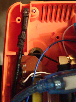 The USB connector that charges the battery.
Of course, what kind of mobile phone would this be if it couldn’t be mobile? No kind of mobile phone, that’s what. The two options for being able to carry the phone wherever I went were either a small, 5 volt battery and a USB charging circuit, or a very, very long cable. Seeing how copper is worth more than gold today, and also how I’m not made of money, I opted for the former.
There are three components we need for this:
- A battery (with its assorted battery holder, as it doesn’t work without it, I tried). This will obviously power the phone and non-obviously be hidden from view inside the phone.
- A charging circuit, one end of which will be connected to the battery and the other will be a female USB connector. This will allow the battery to charge with an ordinary USB charger.
- A regulator (or something, I don’t remember the actual name, but it’s something of the sort). This will be connected to the battery and will rob it of its power, like Kryptonite for batteries. Batteries don’t actually produce the voltage they claim to produce, but they produce less and less as they discharge, and this little circuit will allow the Arduino to receive a consistent 5 volts until the battery dies completely and everything is ruined.
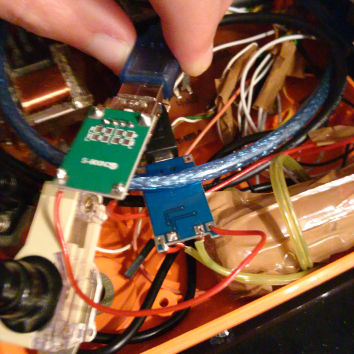 The regulator and charger circuits, connected together.
To recap, and as you can see on the right, the battery and regulator are connected to the charger. The charger also has a USB port (and I used an extension cable to run it all the way to where the original phone cable was), which will be used to charge the battery. The regulator can figure things out, and supply the correct voltages to the correct parts, so you can plug or unplug the phone to charge even while it’s running, and there won’t be a voltage drop.
You can also have the phone charging while it’s on, which is pretty handy. I don’t know how long the battery will last, as I haven’t tried running it for more than a few hours, but it’s probably a day or two, since it’s not like you can exactly text your friends on it (you need the typewriter addon for that). I should try testing it at some point, and will update this post if I ever do (which means that I haven’t yet), but, for now, I’ll claim that it has a few months of battery life and weeks of talk time, as it will definitely get it to sell better, or at least get the Kickstarter to reach the goal pretty quickly.
Step 5: There is no step 5
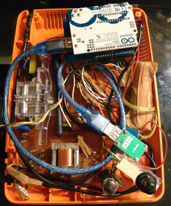 The internals, hooked up to completion.
The project was finally done! After some cabling and general making-things-fit-in-places-they-weren’t-meant-to, the phone’s shell can be closed again with everything fitting snuggly inside it, as long as you don’t shake it too hard.
You can see roughly the positions of all the components in the photo on the right. The Arduino is at the top right, with the shield connected under it (you can see the antenna sticking out of it), the blue USB cable that powers it runs to the regulator, which is connected to the battery and charger, which then runs to the female USB jack at the top left. You can also see the cables for the microphone and headset (top right corner to bottom left corner.
The circuits on the brown board, on the underside of the phone, are the original circuits of the phone. They aren’t used for anything now, but it would be too hard to remove them, and they may have made the hook (the transparent piece of plastic on the left) not work, which was unacceptable.
And, as promised, I present to you the final trailer, in all its final glory. What a sight to behold! Make sure to send it to all your friends, even the ones you haven’t talked to in a while. What’s more important than reconnecting with old friends over some crazy internet project by a dude in Greece? That’s right, nothing!
If you’re itching to create your own rotary mobile phone, and are thinking of writing everything from scratch by spending endless nights reverse-engineering the tiny snippets I’ve posted here, I have good news. I have published the code for the entire thing, because that’s just the kind of guy I am:
https://github.com/skorokithakis/iRotary
Please tell me how much this amazing project has changed your life in the comments below, or directly on Twitter. Kisses!